Laser Marking Field Size Guide: 110×110 vs 150×150 vs 200×200 vs 300×300 mm
Last updated: September 22, 2026
Short answer
Choose a laser marking field from the size of the content that must be marked—not from the outside dimensions of the workpiece alone. A 300 × 200 mm nameplate may need only an 80 × 40 mm logo-and-code area, while a much smaller part may need a larger field if several pieces are marked in one fixture.
A larger field gives the scanner more working area, but it can also change spot size, working distance, energy density, edge performance and the smallest practical feature. The final choice must therefore combine the artwork, minimum text or code feature, material, laser source, power, required depth or contrast, cycle time and the specific lens/scanner configuration.
Nameplate size does not equal required marking area
The workpiece must fit beneath the marking head and within the mechanical working envelope, but its full outline does not have to fit inside the laser field unless the laser must mark across that full outline.
Use the actual marked content to define the field:
- the logo bounding box;
- the text block;
- the QR or Data Matrix code, including its quiet zone;
- the serial-number or variable-data area;
- any engraved border, scale or filled graphic;
- the distance between separate marked elements;
- fixture and loading tolerance around the content.
For example, consider a 300 × 200 mm metal plate with a 60 × 25 mm logo, a 20 × 20 mm code and two short text lines grouped inside an 85 × 45 mm layout. The plate is large, but the required marking field is approximately the artwork envelope plus practical positioning allowance—not automatically 300 × 200 mm. The machine still needs enough physical clearance for the complete plate and fixture.
Field-size comparison
The table below is a selection guide, not a promise that every field is available with every source or FYXFER machine. Confirm the quoted lens, scanner, wavelength, working distance and tested result as one configuration.
| Nominal marking field | Useful starting applications | Main advantage | What to verify |
|---|---|---|---|
| 110 × 110 mm | Small logos, serial numbers, compact codes, jewelry, tools and small nameplate layouts | Concentrates the available field on smaller work and is often a practical starting point for fine features | Complete artwork envelope, smallest feature, part clearance, fixture position and required depth or contrast |
| 150 × 150 mm | Medium labels, wider text layouts, small multi-part fixtures and jobs that need more placement tolerance than 110 × 110 mm | Adds working area without moving directly to a large field | Whether the added area changes spot performance or cycle time for the actual mark |
| 200 × 200 mm | Larger identification plates, grouped parts, medium panels and distributed content | Covers a broader layout or more parts in one fixture | Code cell size, edge-of-field quality, flatness, focus, energy density and complete cycle time |
| 300 × 300 mm | Large layouts, large panels and multi-up fixtures where a single scan field is valuable | Reduces repositioning when the complete marked layout genuinely needs a large area | Minimum feature size, optical compatibility, working distance, field calibration, available process window and whether an XY stage or indexed fixture would give a better result |
An intermediate 175 × 175 mm field is not listed as a standard FYXFER option because the current public FYXFER product pages do not publish it as part of the product system. If that field is offered for a specific scanner and source, add it only after the exact lens and working distance are confirmed in the quotation.
What changes when the marking field gets larger?
Working area and working distance
A larger field normally uses a different scan-lens configuration and often a longer focal length. That can provide a larger working area and a different working distance. It also changes how the head, lens, part and fixture fit together, so the physical clearance must be checked with the actual workpiece in place.
Spot performance and energy density
A larger field does not simply enlarge the same process. Depending on the wavelength, input beam, scanner aperture and lens design, the focused spot may become larger. The available laser energy is then distributed differently at the workpiece. This can affect fine detail, edge definition, engraving depth, contrast and marking speed.
Do not turn this relationship into a universal wattage rule. A 300 × 300 mm field does not always require a particular power, and a higher-power source does not automatically restore the detail of a smaller optical field.
Edge-of-field performance
Lens design, scanner calibration, beam alignment and focus all influence the result near the edge of the field. If critical text, a verification code or a fine border approaches the field limit, test it in the intended position rather than approving only a sample made at the center.
Fixture strategy and cycle time
A large field can mark several components in one fixture, but that is useful only when part positions are repeatable and the complete cycle improves. Compare loading, positioning, marking and inspection time—not scan time alone. For some jobs, a smaller field plus an indexed fixture or motion stage can provide better feature quality and process control.
Choose the field from the artwork
Use this sequence before selecting a lens:
- Draw the smallest rectangle that contains every element to be marked.
- Record the smallest text stroke, line, code cell or other critical feature.
- Add the real fixture and loading tolerance required by the process.
- Confirm whether several parts will be marked in one loading cycle.
- Define the required result: surface contrast, color effect, shallow etch or engraving depth.
- State the material grade, coating and surface finish.
- Set an acceptable complete cycle time and inspection method.
- Test the proposed source, lens and field on a representative part.
Do not add excessive unused margin “just in case.” Extra field area can carry an optical trade-off without creating value for the job.
Typical selection examples
| Job | Workpiece size | Actual marked content | Sensible first comparison |
|---|---|---|---|
| Small pendant with a logo and two initials | 35 × 25 mm | 18 × 12 mm | Start with the smallest suitable field; among the four fields on this page, compare 110 × 110 mm first |
| Large rating plate with a compact data block | 300 × 200 mm | 85 × 45 mm | Evaluate 110 × 110 mm if the fixture can position the data block reliably |
| Control panel with labels spread across one area | 220 × 180 mm | Approximately 195 × 155 mm overall | Evaluate 200 × 200 mm and verify the smallest text at the field edges |
| Six small tags in one fixture | Each tag 40 × 20 mm | Multi-up layout 145 × 90 mm | Compare 150 × 150 mm with a smaller field and indexed loading; use complete cycle time to decide |
| Large plate with content distributed over 270 × 260 mm | 350 × 320 mm | 270 × 260 mm | Evaluate 300 × 300 mm only after optical compatibility and the minimum feature are tested |
These examples illustrate the selection method. They are not guaranteed machine configurations.
Match the lens to the source, material and result
Field size cannot be selected in isolation. The following variables work together:
- Laser source: conventional fiber, MOPA, UV and CO2 sources have different wavelengths and pulse behavior. The lens must be designed for the source and scanner.
- Rated power and pulse behavior: available power, pulse energy, pulse width and frequency range affect the process window, but more power is not a substitute for suitable optics.
- Material and finish: stainless steel, anodized aluminum, coated metal, plastic, glass and organic materials respond differently.
- Mark type: fine surface identification, black or color effects, deep engraving and coating removal place different demands on the optical system.
- Artwork: a large filled logo can require a different cycle from sparse text inside the same field.
- Production target: loading, positioning, scan time, inspection and reject rate all belong in the cycle calculation.
The 20W vs 30W vs 50W fiber laser guide explains why power must be selected with the field, artwork and tested result rather than by wattage alone.
Can a 30W MOPA source use a 300 × 300 mm lens?
There is no reliable yes-or-no answer from “30W MOPA” alone. A proposed configuration may be mechanically and optically compatible, but compatibility does not prove that it will meet the required feature size, blackness, color, engraving depth or cycle time.
Ask the supplier to confirm:
- the exact MOPA source model and its pulse-control range;
- the scan head, aperture and compatible 300 × 300 mm lens;
- wavelength and lens coating;
- working distance and part clearance;
- expected spot performance across the field;
- the actual artwork, material and surface finish used for the test;
- marking time and complete cycle time;
- the acceptance method for contrast, depth, color or code readability.
Approve the combination from a representative sample, not from power and field size alone.
Common field-size mistakes
Matching the lens to the outside size of the part
This can oversize the field when the artwork occupies only a small section. Separate mechanical clearance from the marked-content envelope.
Choosing the largest field for future flexibility
Unused area is not free. Confirm that the future job is real and that its minimum feature still works with the proposed optics.
Ignoring the smallest code cell or text stroke
The overall logo may fit while its fine detail does not meet the visual or verification requirement. Supply the original artwork and code specification.
Comparing center samples only
When content spans a large field, test critical features at their intended locations, including near the edges.
Using power as the only correction
Increasing rated power cannot by itself correct unsuitable spot size, focus, beam delivery, line spacing, fixture movement or material variation.
Forgetting the complete part and fixture envelope
The artwork may fit the laser field while the part, rotary device or fixture does not fit beneath the head at the required working distance.
Information to send for a field-lens recommendation
Provide:
- a dimensioned part drawing or clear photograph;
- complete part dimensions and weight;
- vector artwork or the real code layout;
- actual marking-content width and height;
- smallest text, line or code cell;
- material grade, coating and surface finish;
- required contrast, color, depth or readability target;
- number of parts per fixture;
- target output and complete cycle time;
- any rotary axis, enclosure, extraction or automation requirement;
- installation space and electrical supply.
Frequently asked questions
What marking field should I choose for jewelry?
Choose from the artwork and required detail, not from the jewelry box or fixture size. For small pendants, tags and compact personalization, 110 × 110 mm is a practical first comparison among the fields in this guide. Very fine work may benefit from a smaller field if a compatible lens is offered. Rings can also require a rotary fixture and a separate clearance check.
Is 200 × 200 mm enough for nameplates?
It is enough only when the complete marked layout, positioning allowance and required features fit inside that field and pass the sample test. A nameplate larger than 200 × 200 mm can still use a smaller field if the laser marks only one compact area. Conversely, a 200 × 200 mm plate can require another handling method when content reaches the edges or must be marked in several positions.
Can a 30W MOPA use a 300 × 300 mm lens?
Possibly, but the source rating alone does not establish compatibility or process performance. Confirm the exact source, scanner, aperture, lens, working distance and tested result. Do not assume that every 30W MOPA configuration can deliver the same detail, blackness, depth or speed across a 300 × 300 mm field.
Does a larger lens reduce marking quality?
Not automatically, but a larger field can change spot size, energy density, working distance and edge performance depending on the complete optical configuration. Quality should be defined by the real feature, material and acceptance test, then verified across the required field.
Does nameplate size equal marking area?
No. The nameplate is the physical workpiece; the marking area is the envelope containing the logo, text, code, serial number or engraving that the laser must process. Check both the mechanical part clearance and the optical marking field, but do not treat them as the same dimension.
Review an FY-LMM02 field configuration
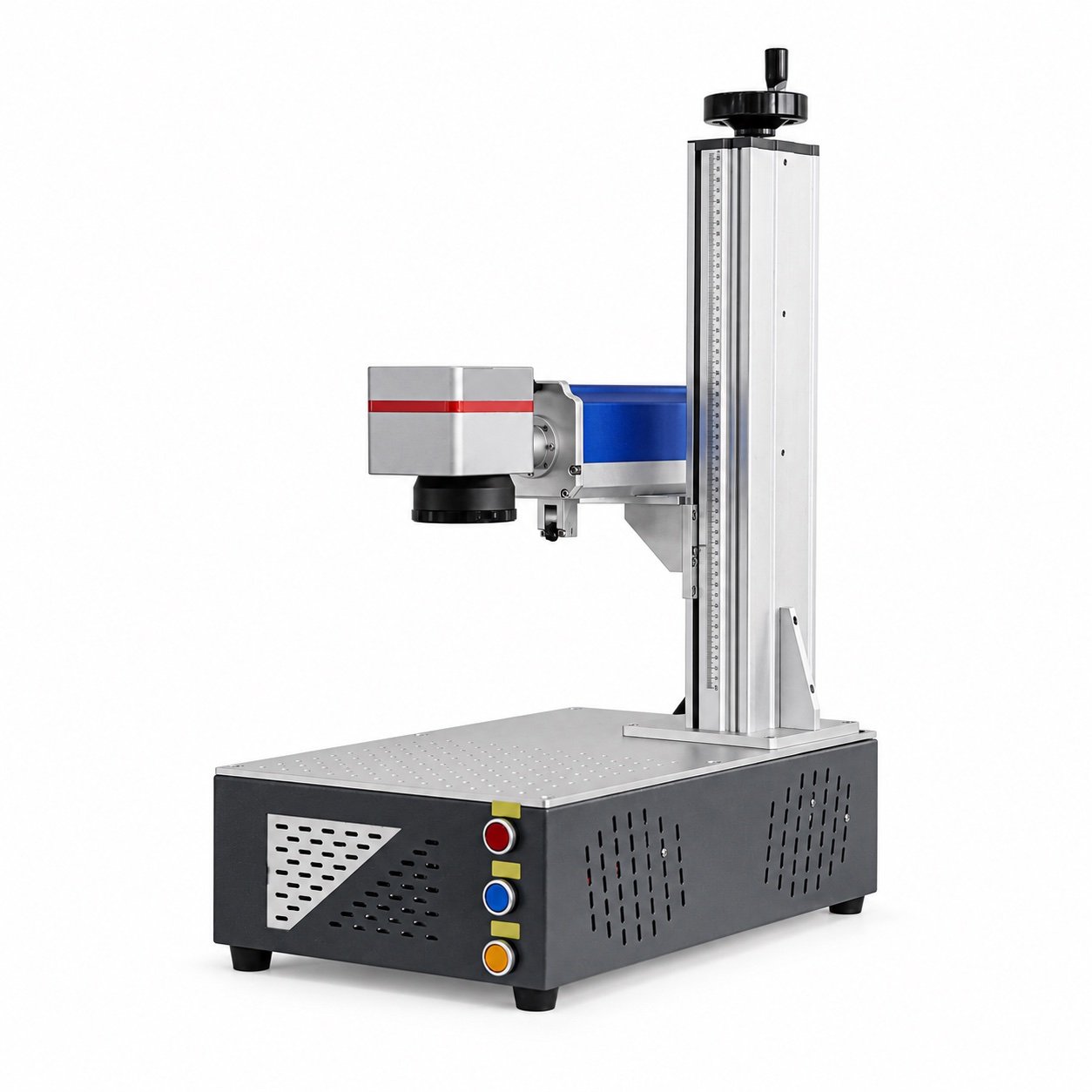
The FY-LMM02 desktop laser marking and engraving machine is a manually loaded, integrated desktop platform. Its source, rated power, lens, marking field, working envelope and fixture are selected for the job; the public product page does not claim that every field in this guide fits every FY-LMM02 configuration.
Compare other workstation formats in FYXFER laser marking machines and review the laser source technologies before finalizing the lens.
Send the part, artwork and required marking area for an FY-LMM02 configuration review