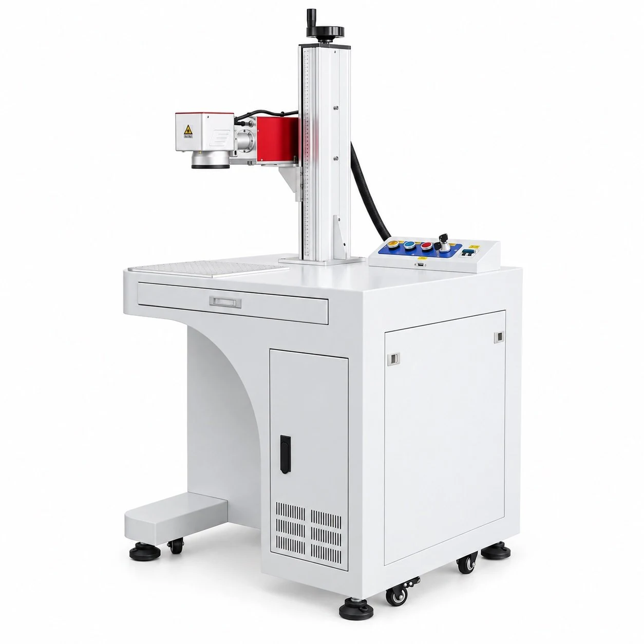
FY-LMM01
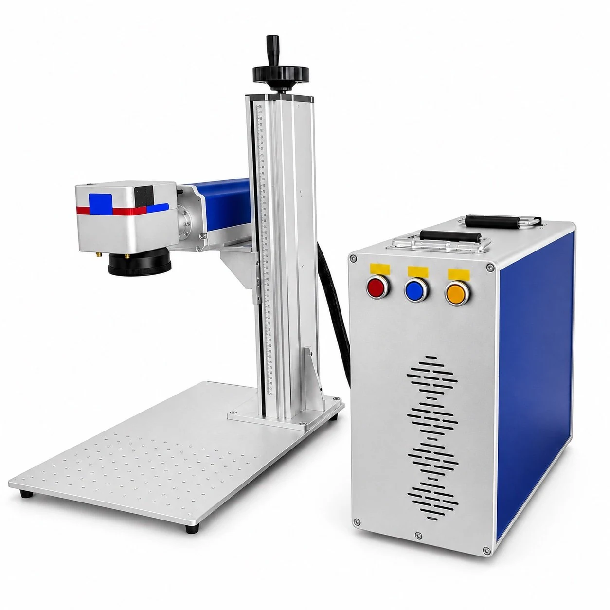
Floor-standing Open
- Stable integrated cabinet
- Open access for varied parts
- Fixture and rotary options
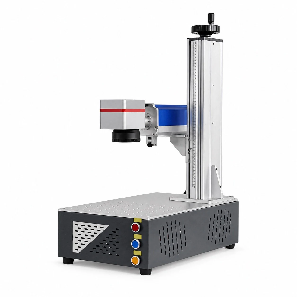
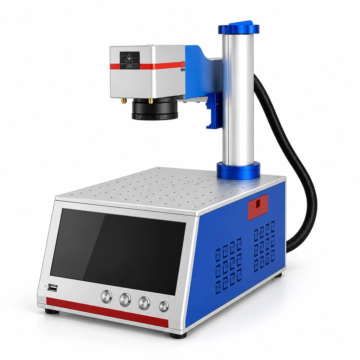
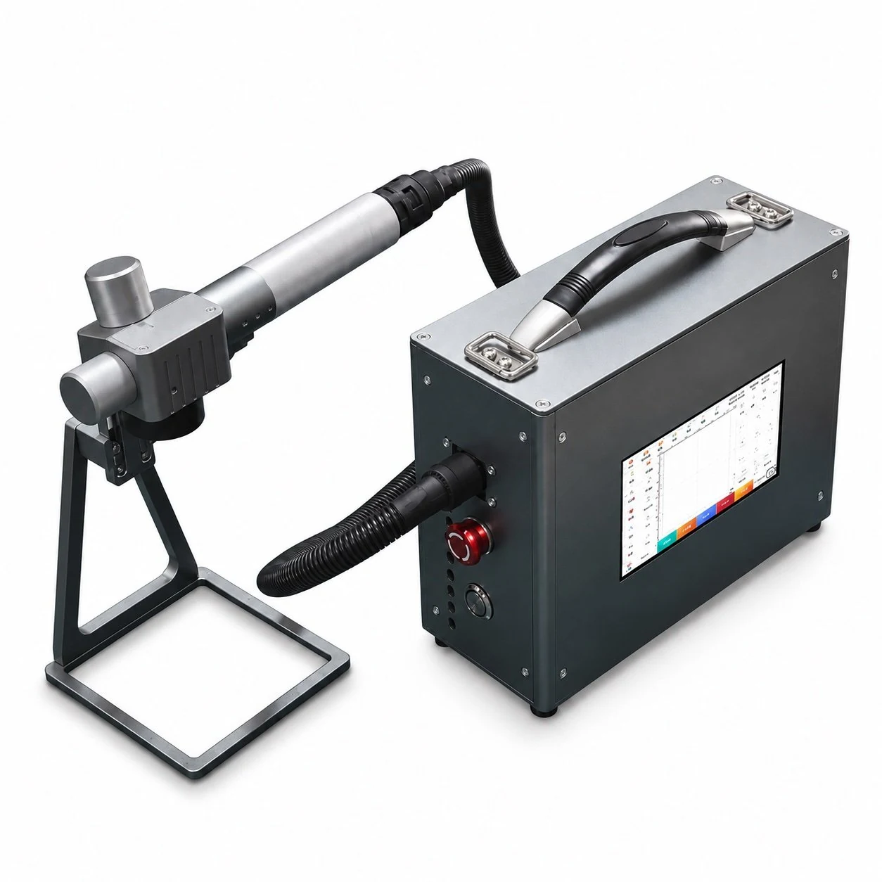
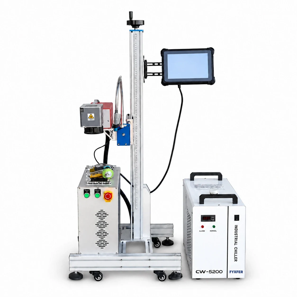
The FY-LMM range covers four ways to present a part to the laser: a floor standing workstation, a desktop unit, a production line and a handheld head. Choose the working arrangement before confirming the laser source and accessories.
Match the equipment to the material, part and production workflow.
Confirm the final equipment and configuration in the quotation.
Fiber, CO₂, UV, green, MOPA, or another source; rated power, wavelength, pulse behavior, lens, and working field are confirmed for the material and mark.
Marking speed, line speed, cycle time, line width, depth, contrast, and code readability are verified against an approved sample or application test.
Power supply, cooling, extraction, computer, software, rotary axis, fixtures, interfaces, guarding, and destination-market requirements are quoted by project.
Match the equipment to the material, part and production workflow.
Browse laser marking, engraving and sample cutting demonstrations. Each video description links to the relevant product or application page. Demonstration results apply to the shown setup and material.
Browse laser marking, engraving and sample cutting demonstrations. Each video description links to the relevant product or application page. Demonstration results apply to the shown setup and material.
View all FYXFER LASER videos on YouTube
Confirm the final equipment and configuration in the quotation.
The correct enclosure or frame is determined by how the part reaches the marking field, how the operator works, and what must be integrated around the laser.
The correct enclosure or frame is determined by how the part reaches the marking field, how the operator works, and what must be integrated around the laser.
Useful when part sizes change and unrestricted access is important. The final safety arrangement must match the installed process.
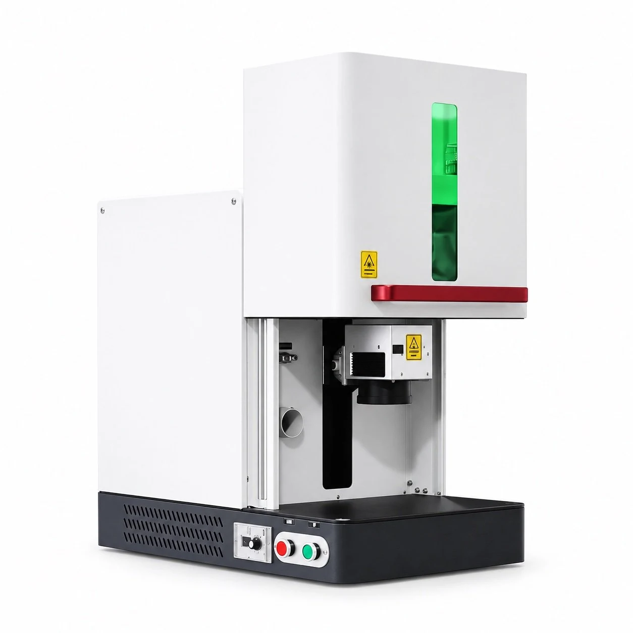
Supports controlled access, guarding, viewing, and extraction for repeatable manual loading.
Consider when the workpiece is too large, heavy, fixed, or awkward to place beneath a conventional marking head.
Specify line speed, sensor and encoder signals, code source, reject logic, communications, and verification before integration.
Confirm the final equipment and configuration in the quotation.
Compare eight machine platforms, then match the laser source, part handling and required mark.
FY-LMM01 · FY-LMM01-C · FY-LMM02 · FY-LMM02-C · FY-LMM03 · FY-LMM04 · FY-LMM05 · FY-LMM07
PDF · English · 127.7 KB FYXFER_Laser_Marking_Selection_Guide_EN.pdf
Confirm the final equipment and configuration in the quotation.
Confirm the final equipment and configuration in the quotation.
| FY-LMM01 | Floor-standing open workstation | Open access for varied parts | Laser source, lens, Z-axis, fixture, rotary axis, extraction |
|---|---|---|---|
| FY-LMM01-C | Floor-standing enclosed workstation | Guarded door and viewing window | Internal working envelope, interlock, extraction, fixture, rotary axis |
| FY-LMM02 | Desktop all-in-one workstation | Open bench-top loading | Laser source, lens, column travel, fixture and software |
| FY-LMM02-C | Desktop enclosed workstation | Controlled chamber access | Chamber size, interlock, extraction, lens and fixture |
| FY-LMM03 | Desktop split-type workstation | Flexible part and cabinet placement | Column height, cable layout, lens, fixture and rotary axis |
| FY-LMM07 | Foldable desktop all-in-one | Portable open workstation | Laser source, marking field, transport setup and positioning |
| FY-LMM05 | Handheld laser marker | Portable head for large or fixed parts | Head weight, cable length, positioning guide, safety and extraction |
| FY-LMM04 | Flying in-line laser marker | Automatic production-line operation | Line speed, encoder, sensor, code source, communications and reject logic |
The model code identifies the mechanical platform. Laser source, power, lens, working field, extraction, fixtures, software, and automation are selected after the material and required mark are reviewed.
| Model | Machine format | Operator access | Project-specific configuration |
|---|---|---|---|
| FY-LMM01 | Floor-standing open workstation | Open access for varied parts | Laser source, lens, Z-axis, fixture, rotary axis, extraction |
| FY-LMM01-C | Floor-standing enclosed workstation | Guarded door and viewing window | Internal working envelope, interlock, extraction, fixture, rotary axis |
| FY-LMM02 | Desktop all-in-one workstation | Open bench-top loading | Laser source, lens, column travel, fixture and software |
| FY-LMM02-C | Desktop enclosed workstation | Controlled chamber access | Chamber size, interlock, extraction, lens and fixture |
| FY-LMM03 | Desktop split-type workstation | Flexible part and cabinet placement | Column height, cable layout, lens, fixture and rotary axis |
| FY-LMM07 | Foldable desktop all-in-one | Portable open workstation | Laser source, marking field, transport setup and positioning |
| FY-LMM05 | Handheld laser marker | Portable head for large or fixed parts | Head weight, cable length, positioning guide, safety and extraction |
| FY-LMM04 | Flying in-line laser marker | Automatic production-line operation | Line speed, encoder, sensor, code source, communications and reject logic |
Browse laser marking, engraving and sample cutting demonstrations. Each video description links to the relevant product or application page. Demonstration results apply to the shown setup and material.
View all FYXFER LASER videos on YouTube
The model code identifies the mechanical platform. Laser source, power, lens, working field, extraction, fixtures, software, and automation are selected after the material and required mark are reviewed.
Fiber, CO₂, UV, green, MOPA, or another source; rated power, wavelength, pulse behavior, lens, and working field are confirmed for the material and mark.
Marking speed, line speed, cycle time, line width, depth, contrast, and code readability are verified against an approved sample or application test.
Power supply, cooling, extraction, computer, software, rotary axis, fixtures, interfaces, guarding, and destination-market requirements are quoted by project.
| Model | Machine format | Operator access | Project-specific configuration |
|---|---|---|---|
| FY-LMM01 | Floor-standing open workstation | Open access for varied parts | Laser source, lens, Z-axis, fixture, rotary axis, extraction |
| FY-LMM01-C | Floor-standing enclosed workstation | Guarded door and viewing window | Internal working envelope, interlock, extraction, fixture, rotary axis |
| FY-LMM02 | Desktop all-in-one workstation | Open bench-top loading | Laser source, lens, column travel, fixture and software |
| FY-LMM02-C | Desktop enclosed workstation | Controlled chamber access | Chamber size, interlock, extraction, lens and fixture |
| FY-LMM03 | Desktop split-type workstation | Flexible part and cabinet placement | Column height, cable layout, lens, fixture and rotary axis |
| FY-LMM07 | Foldable desktop all-in-one | Portable open workstation | Laser source, marking field, transport setup and positioning |
| FY-LMM05 | Handheld laser marker | Portable head for large or fixed parts | Head weight, cable length, positioning guide, safety and extraction |
| FY-LMM04 | Flying in-line laser marker | Automatic production-line operation | Line speed, encoder, sensor, code source, communications and reject logic |
The correct enclosure or frame is determined by how the part reaches the marking field, how the operator works, and what must be integrated around the laser.
Useful when part sizes change and unrestricted access is important. The final safety arrangement must match the installed process.
Supports controlled access, guarding, viewing, and extraction for repeatable manual loading.
Consider when the workpiece is too large, heavy, fixed, or awkward to place beneath a conventional marking head.
Specify line speed, sensor and encoder signals, code source, reject logic, communications, and verification before integration.
Compare eight machine platforms, then match the laser source, part handling and required mark.
FY-LMM01 · FY-LMM01-C · FY-LMM02 · FY-LMM02-C · FY-LMM03 · FY-LMM04 · FY-LMM05 · FY-LMM07
PDF · English · 127.7 KB FYXFER_Laser_Marking_Selection_Guide_EN.pdf
Send the part size, material, marking field, output, and loading method. We will narrow the machine form first.
Metal identification, traceability and engraving from actual part requirements.
Broader pulse control for selected color, black and heat-sensitive applications.
Marking and engraving for many organic and non-metal materials.
Fine, low-heat marking on selected plastics, glass, electronics and packaging.
FY-LMM01 Floor-Standing Laser Marking Machine
FY-LMM02 Desktop Integrated Laser Marker
FY-LMM04 Flying Laser Marking Machine
FY-LMM05 Handheld Laser Marking Machine
FYXFER® Industrial Machinery is the industrial equipment brand of Yangzhou Fengyue CNC Technology Co., Ltd., a China-based manufacturer founded in 1996.
Laser marking, engraving and cutting systems are configured around the material, result, part handling and production workflow. OEM, ODM and custom projects can include sample review, multi-site coordination, remote technical support, spare parts and after-sales service.
Where CE documentation applies, confirm it for the selected machine and quoted configuration.
Review the integrated desktop platform, real machine photographs, field-lens options and configuration checklist before requesting a quote.
Identify the material and surface finish, then send the part dimensions, artwork, required contrast or depth and output per shift.
Compare fiber laser cutting formats for sheet metal and industrial fabrication.
Confirm the selected equipment, fixtures, utilities, installation needs and supply scope before ordering.
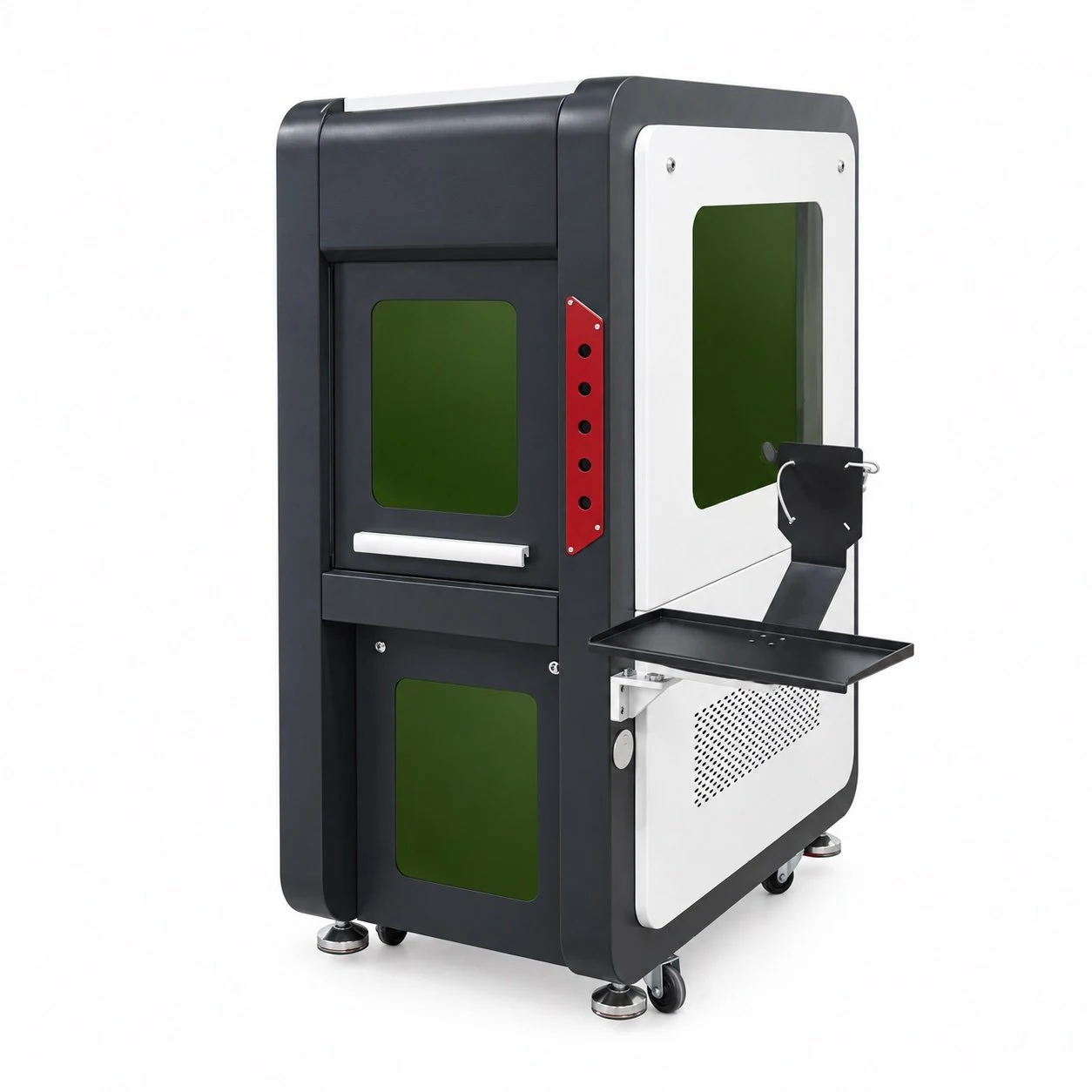
Consider FY-LMM01-C for a floor-standing marking station with an enclosure, access door and viewing window. Select the chamber, workholding and laser configuration together, using the largest complete part setup as the starting point.
Confirm the final equipment and configuration in the quotation.
Evaluate the enclosed format when the same part family can be positioned, marked and removed through a defined loading opening.
Review text, logos or codes with the required material, artwork and acceptance criteria before specifying the laser process.
Plan fixture mounting and any rotary arrangement within the available chamber and lens working distance.
Match the equipment to the material, part and production workflow.
A component that fits inside a chamber may still be awkward to load or rotate. Review the complete setup with the door open and closed.
Request the current chamber drawing. The category listing does not establish internal dimensions, door clearance or a maximum workpiece size.
Confirm the final equipment and configuration in the quotation.
Define access control, viewing and extraction with the selected source and installation. Exterior enclosure photographs alone cannot establish the complete protective arrangement.
No. Confirm the supplied machine's guarding, access-control and viewing specification, together with the relevant documentation for the installation.
Confirm the final equipment and configuration in the quotation.
Select source and optics from the material and artwork. Include door movement and part handling when checking whether the workstation meets the production target.
The enclosure defines the workstation format. Process speed and mark quality depend on the selected source, optics, material, artwork and operating sequence.
Confirm the final equipment and configuration in the quotation.
Confirm the final equipment and configuration in the quotation.
| Machine format | FY-LMM01-C floor-standing enclosed workstation |
|---|---|
| Operator access | Door and viewing window listed in the model category |
| Internal envelope | Request chamber and loading-opening drawings |
| Source / power / field | Confirm an application-specific configuration |
| Workholding | Confirm fixture mounting and rotary clearance |
| Access controls | Confirm interlock and guarding details |
| Extraction | Extraction-ready enclosure listed; confirm supplied scope |
| Installation / acceptance | Confirm utilities, footprint, documentation and sample test |
Compare it when parts vary widely in shape or access requirements. Evaluate both formats against part handling, the selected process and the required protective arrangement.
The category identifies rotary configuration as project-specific. Confirm the device, workpiece clearance, controls and included accessories in the quotation.
Obtain the current source and lens specification, chamber drawing, fixture proposal, installation requirements and agreed sample-acceptance record.
Share the largest part and fixture dimensions, marking position, material, artwork and output target. Request an FY-LMM01-C chamber drawing and proposed configuration before confirming fit.
Continue on our contact page to share your application and request a configuration.
Discuss my application ↗FY-LMM07 is listed as a foldable desktop all-in-one platform with an integrated control layout. Review the deployed workspace, transport arrangement and part positioning before choosing its source, lens and marking application.
Confirm the final equipment and configuration in the quotation.
Evaluate the deployed platform with the complete part and fixture, allowing room for loading and operator access.
Review transport, storage and recommissioning requirements when a marking workstation needs to move between approved locations.
Consider repeatable identification jobs after checking workholding, focus setting and the proposed process on representative material.
Match the equipment to the material, part and production workflow.
A compact storage format does not define the space needed for marking. Review the operating footprint, head position, part envelope and access together.
Request the current machine drawing. The model category does not establish working-envelope dimensions or maximum workpiece capacity.
Confirm the final equipment and configuration in the quotation.
Confirm how the unit is folded, secured and moved, then define the checks needed when it is installed again. Review the actual handling requirements before relying on frequent relocation.
That is not established by the category listing. Confirm the supplied machine weight, handling instructions and transport arrangement.
Confirm the final equipment and configuration in the quotation.
Portability describes the machine format. Material response, optics, stable positioning and the operating environment still determine whether a marking job is suitable.
Check setup, focus and positioning at each intended location. Approve the result on representative material under the proposed operating conditions.
Confirm the final equipment and configuration in the quotation.
Confirm the final equipment and configuration in the quotation.
| Machine format | FY-LMM07 foldable desktop all-in-one |
|---|---|
| Control layout | Integrated layout listed in the model category |
| Working envelope | Request deployed drawing and part-clearance details |
| Transport / storage | Confirm dimensions, weight, protection and handling |
| Laser source / power | Application-specific; request current configuration |
| Lens / field | Confirm artwork, detail and working distance |
| Part positioning | Confirm fixture and focus-setting arrangement |
| Installation scope | Confirm power, extraction, guarding, software and supplied accessories |
It is listed as a foldable desktop workstation. For a head brought directly to a large or fixed component, compare the FY-LMM05 handheld format.
Material suitability must be assessed with the selected source, optics and required mark. The category listing does not establish a universal material range.
Provide material, artwork, part dimensions, available workspace and how often the station will move. Request the current configuration and installation drawings.
Send your part, material and artwork, plus available bench space and transport needs. Request FY-LMM07 deployed dimensions and a sample plan before finalising the configuration.
Continue on our contact page to share your application and request a configuration.
Discuss my application ↗Start with your material and application. Add the dimensions, result and production target when known.
Continue on our contact page to share your application and request a configuration.
Discuss my application ↗