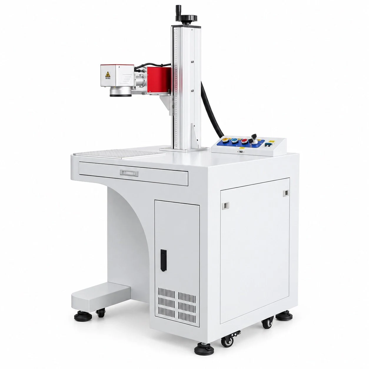
FY-LMM01
FY-LMM01 Floor-Standing Laser Marking Machine
Match the equipment to the material, part and production workflow.
View product ↗FYXFER fiber laser marking machines are configured for permanent identification, surface marking and engraving on metals and selected industrial plastics. Common power options range from 20W to 120W, but power alone does not determine the result. We match the source, lens, working field, machine format, fixture, software and safety arrangement to your material, mark and production workflow.
Material.
Result.
Configuration.
Match the equipment to the material, part and production workflow.
Match the equipment to the material, part and production workflow.
View product ↗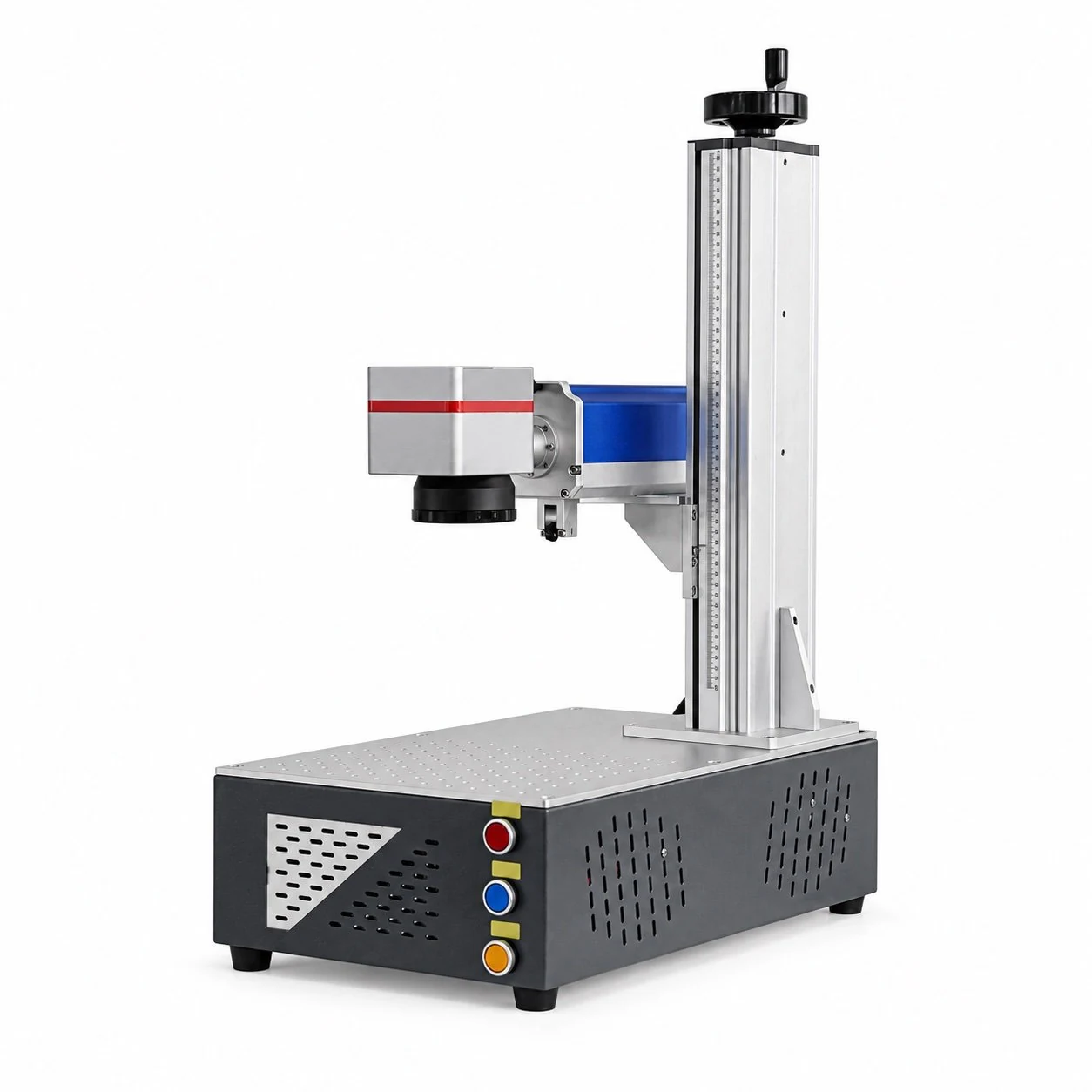
Match the equipment to the material, part and production workflow.
View product ↗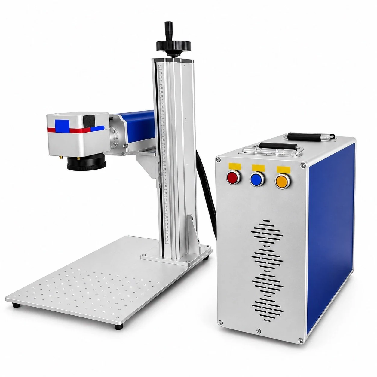
Match the equipment to the material, part and production workflow.
View product ↗Confirm the final equipment and configuration in the quotation.
Apply part numbers, date codes, barcodes, QR codes and data-matrix codes to production components. Code size, readability target, content source and verification method should be defined before configuration.
Create logos, scales, labels and identification graphics through surface change, annealing or coating removal where the material supports the required effect.
Fiber systems can be evaluated for visible engraving depth on suitable metals. Required depth, filled area, edge quality and cycle target affect the appropriate power and process strategy.
Match the equipment to the material, part and production workflow.
Fiber technology is a practical starting point for stainless steel, carbon steel, aluminum, brass, copper alloys, coated metals and selected engineered plastics. Alloy, coating, color, additives and surface finish can change the process window, so representative sample testing is recommended when contrast, depth or code quality is critical.
Fiber technology is a practical starting point for stainless steel, carbon steel, aluminum, brass, copper alloys, coated metals and selected engineered plastics. Alloy, coating, color, additives and surface finish can change the process window, so representative sample testing is recommended when contrast, depth or code quality is critical.
See more use cases on our laser marking applications page.
Apply part numbers, date codes, barcodes, QR codes and data-matrix codes to production components. Code size, readability target, content source and verification method should be defined before configuration.
Create logos, scales, labels and identification graphics through surface change, annealing or coating removal where the material supports the required effect.
Fiber systems can be evaluated for visible engraving depth on suitable metals. Required depth, filled area, edge quality and cycle target affect the appropriate power and process strategy.
Confirm the selected equipment, fixtures, utilities, installation needs and supply scope before ordering.
See a portrait engraved on a pendant. Image preparation, surface finish and marking settings influence detail and contrast.
A small sample demonstration of a cutout in a thin metal can lid. Capability depends on the laser configuration, material, thickness and process; this does not establish sheet-metal production cutting capacity.
Confirm the selected equipment, fixtures, utilities, installation needs and supply scope before ordering.
Lower-power configurations are commonly evaluated for routine surface identification and detailed marks. Mid-range and higher-power systems may provide a more suitable process window for deeper engraving, larger filled areas or shorter cycle targets. The correct choice still depends on the alloy, marking field, lens, artwork and acceptance standard; a higher wattage does not automatically produce a better mark.
Lower-power configurations are commonly evaluated for routine surface identification and detailed marks. Mid-range and higher-power systems may provide a more suitable process window for deeper engraving, larger filled areas or shorter cycle targets. The correct choice still depends on the alloy, marking field, lens, artwork and acceptance standard; a higher wattage does not automatically produce a better mark.
Send the smallest feature, largest filled area, required depth or contrast, part dimensions and expected output. FYXFER can then define which powers should be included in sample testing.
For broader pulse-width control, compare our MOPA laser marking machines .
If the requirement is a dark stainless-steel mark, compare standard fiber and MOPA on the actual part . Record surface finish, contrast, heat effect and accepted output to decide whether additional pulse control is useful.
Confirm the selected equipment, fixtures, utilities, installation needs and supply scope before ordering.
Fiber technology is a practical starting point for stainless steel, carbon steel, aluminum, brass, copper alloys, coated metals and selected engineered plastics. Alloy, coating, color, additives and surface finish can change the process window, so representative sample testing is recommended when contrast, depth or code quality is critical.
See more use cases on our laser marking applications page.
Apply part numbers, date codes, barcodes, QR codes and data-matrix codes to production components. Code size, readability target, content source and verification method should be defined before configuration.
Create logos, scales, labels and identification graphics through surface change, annealing or coating removal where the material supports the required effect.
Fiber systems can be evaluated for visible engraving depth on suitable metals. Required depth, filled area, edge quality and cycle target affect the appropriate power and process strategy.
See a portrait engraved on a pendant. Image preparation, surface finish and marking settings influence detail and contrast.
A small sample demonstration of a cutout in a thin metal can lid. Capability depends on the laser configuration, material, thickness and process; this does not establish sheet-metal production cutting capacity.
Lower-power configurations are commonly evaluated for routine surface identification and detailed marks. Mid-range and higher-power systems may provide a more suitable process window for deeper engraving, larger filled areas or shorter cycle targets. The correct choice still depends on the alloy, marking field, lens, artwork and acceptance standard; a higher wattage does not automatically produce a better mark.
Send the smallest feature, largest filled area, required depth or contrast, part dimensions and expected output. FYXFER can then define which powers should be included in sample testing.
For broader pulse-width control, compare our MOPA laser marking machines .
If the requirement is a dark stainless-steel mark, compare standard fiber and MOPA on the actual part . Record surface finish, contrast, heat effect and accepted output to decide whether additional pulse control is useful.
Fiber technology is a practical starting point for stainless steel, carbon steel, aluminum, brass, copper alloys, coated metals and selected engineered plastics. Alloy, coating, color, additives and surface finish can change the process window, so representative sample testing is recommended when contrast, depth or code quality is critical.
See more use cases on our laser marking applications page.
Apply part numbers, date codes, barcodes, QR codes and data-matrix codes to production components. Code size, readability target, content source and verification method should be defined before configuration.
Create logos, scales, labels and identification graphics through surface change, annealing or coating removal where the material supports the required effect.
Fiber systems can be evaluated for visible engraving depth on suitable metals. Required depth, filled area, edge quality and cycle target affect the appropriate power and process strategy.
See a portrait engraved on a pendant. Image preparation, surface finish and marking settings influence detail and contrast.
A small sample demonstration of a cutout in a thin metal can lid. Capability depends on the laser configuration, material, thickness and process; this does not establish sheet-metal production cutting capacity.
Lower-power configurations are commonly evaluated for routine surface identification and detailed marks. Mid-range and higher-power systems may provide a more suitable process window for deeper engraving, larger filled areas or shorter cycle targets. The correct choice still depends on the alloy, marking field, lens, artwork and acceptance standard; a higher wattage does not automatically produce a better mark.
Send the smallest feature, largest filled area, required depth or contrast, part dimensions and expected output. FYXFER can then define which powers should be included in sample testing.
For broader pulse-width control, compare our MOPA laser marking machines .
If the requirement is a dark stainless-steel mark, compare standard fiber and MOPA on the actual part . Record surface finish, contrast, heat effect and accepted output to decide whether additional pulse control is useful.
For organic and many non-metal materials, review CO2 laser marking machines ; for fine, low-heat work, review UV laser marking machines .
Choose an open, enclosed, desktop, floor-standing, handheld or in-line platform according to part size, loading method, operator access and integration needs.
Confirm the marking field, focal requirements, Z-axis travel, fixture and rotary axis. Cylindrical, recessed or irregular parts may need dedicated handling.
Define fixed artwork, counters, serial-number rules, database content, sensors, PLC communication and code verification before an automated system is specified.
No single setting suits every alloy, coating and finish. The exact contrast, depth and cycle should be verified on the intended production material.
Choose after reviewing the required result rather than wattage alone. Surface marks, deep engraving, large filled graphics and cycle targets can lead to different recommendations.
Send the material grade and finish, part photos and dimensions, artwork, field size, desired result, output target, loading method and destination requirements.
Share your material, artwork, dimensions and required result. FYXFER will review the application before recommending a power range and machine format.
Fiber laser marking machine for metal · Fiber vs MOPA · 20W vs 30W vs 50W · Stainless-steel marking
Review the integrated desktop platform, real machine photographs, field-lens options and configuration checklist before requesting a quote.
Identify the material and surface finish, then send the part dimensions, artwork, required contrast or depth and output per shift.
Compare fiber laser cutting formats for sheet metal and industrial fabrication.
No single setting suits every alloy, coating and finish. The exact contrast, depth and cycle should be verified on the intended production material.
Choose after reviewing the required result rather than wattage alone. Surface marks, deep engraving, large filled graphics and cycle targets can lead to different recommendations.
Send the material grade and finish, part photos and dimensions, artwork, field size, desired result, output target, loading method and destination requirements.
Start with your material and application. Add the dimensions, result and production target when known.
Continue on our contact page to share your application and request a configuration.
Discuss my application ↗