Bumper-cover openings
Review opening locations on curved bumper covers; the illustrated application uses PP+EPDM-TD20, which is an example rather than a universal material approval.
A five-axis CO2 reference system for trimming and openings in molded non-metal parts. Match the fixture, taught path and sample result to the component before confirming the installation and production configuration.
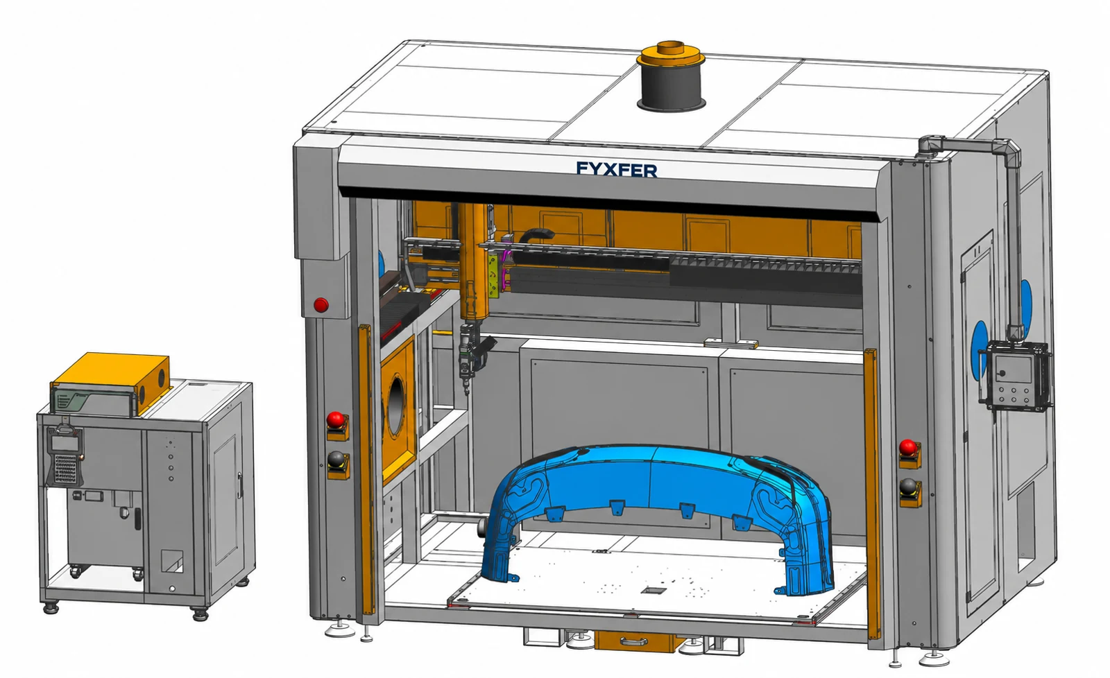
CAD configuration illustration with the enclosure open to show the cutting area. The depicted part and fixture are application examples.
Confirm the final equipment and configuration in the quotation.
Review opening locations on curved bumper covers; the illustrated application uses PP+EPDM-TD20, which is an example rather than a universal material approval.
Assess gate trimming on B-pillar exterior trim with the actual wall section, support points and accepted edge.
Use a matched fixture and saved cutting program for reviewed components, with loading and inspection included in the production discussion.
Match the equipment to the material, part and production workflow.
Three linear axes and the A/C rotary head position the beam along a three-dimensional path. Review the complete workpiece, fixture support and head access around openings and trim lines, not only the component envelope.
Not by itself. The part, fixture, head approach and cutting path must fit within the usable motion and installation arrangement.
CAD configuration illustration with the enclosure open to show the cutting area. The depicted part and fixture are application examples.
Provide the material designation, wall thickness and finish requirement. The bumper material example does not validate every molded polymer; agree the sample conditions and inspect the actual component before setting production acceptance.
No. It is repeat positioning accuracy for the reference machine, not a finished-part tolerance. Part results depend on the material, fixture and process.
CAD configuration illustration with the enclosure open to show the cutting area. The depicted part and fixture are application examples.
Create the path through manual teaching, adjust the settings and save the program. Plan fixture loading and repeat processing together; maximum traverse speed is a motion reference, while cutting speed and cycle time remain application-dependent.
The component, cutting path, material and process settings contribute, along with loading and handling. Confirm a representative job rather than using traverse speed as cutting speed.
CAD configuration illustration with the enclosure open to show the cutting area. The depicted part and fixture are application examples.
Confirm the final equipment and configuration in the quotation.
| Laser reference | 300 W CO2; values below describe this reference configuration. |
|---|---|
| Axes | Five axes: X, Y, Z, A and C. |
| Linear travel | 2300 x 1000 x 800 mm for X / Y / Z. |
| Path programming | Manual teaching with saved cutting programs. |
| Drive system | Servo motors with rack-and-pinion and screw transmission. |
| Maximum traverse speed | 0.5 m/s reference; not the material cutting speed. |
| Repeat positioning | +/-0.05 mm reference; does not establish finished-part tolerance. |
| Laser cooling | Water cooling in the reference arrangement. |
| Machine dimensions | 3600 x 2380 x 3000 mm, excluding auxiliary equipment. |
| Main-machine weight | Approximately 4.5 t for the reference configuration. |
Use these values to assess the available working travel and machine format. Confirm the configuration and process requirements for your component before ordering.
Specifications describe the 300 W reference configuration. Final configuration and process results are confirmed for the material, part geometry and application. Repeat positioning accuracy describes machine positioning and does not establish the cut-part tolerance.
| Laser type | CO2 |
|---|---|
| Rated laser power | 300 W |
| Motion axes | Five axes: X, Y, Z, A and C |
| X / Y / Z travel | 2300 × 1000 × 800 mm |
| Path programming | Manual teaching |
| Drive system | Servo motors with rack-and-pinion and screw transmission |
| Maximum traverse speed | 0.5 m/s |
| Repeat positioning accuracy | ±0.05 mm |
| Cutting speed | Application-dependent; determined by material, thickness, laser settings and cutting path |
| Laser cooling | Water cooling |
| Overall machine dimensions | 3600 × 2380 × 3000 mm, excluding auxiliary equipment |
| Main-machine weight | Approximately 4.5 t |
This system is described for three-dimensional trimming and hole cutting on molded non-metal parts, not as a general-purpose metal sheet-cutting platform.
It shows the reference cutting-zone arrangement, extraction provisions and fixture concept. Final auxiliary layout and machine details require configuration review.
No. They describe the machine configuration. Material suitability, finished geometry and cutting performance must be confirmed for the application.
Send a 3D model or drawing, material designation, wall thickness, trim lines and acceptance criteria. Add your fixture concept, target cycle and available installation space.
Continue on our contact page to share your application and request a configuration.
Discuss my application ↗