Parts, tags and plates
Review component identification with text, logos, serials or machine-readable codes on the intended production material.
FY-LMM03 separates the marking stand from the control cabinet for a flexible bench layout. Manual height adjustment and an operator-loaded worktable support application-specific source, lens and fixture selection.
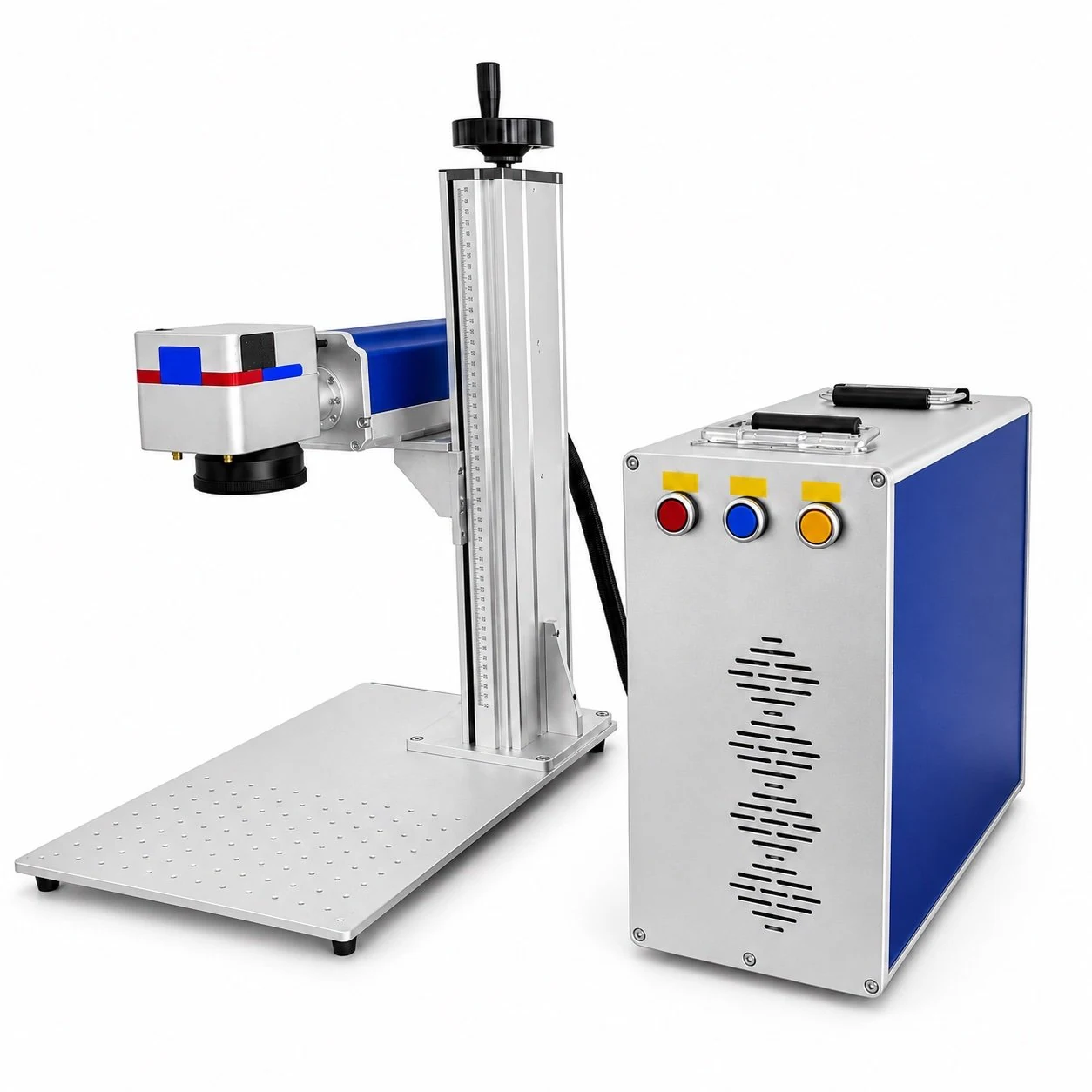
Split configuration with manual height adjustment. Accessories are confirmed with the order.
Confirm the final equipment and configuration in the quotation.
Review component identification with text, logos, serials or machine-readable codes on the intended production material.
Use an appropriate fixture, saved job settings and first-piece checks to support a repeatable loading sequence.
Evaluate the optional rotary device against diameter, length, weight, marking position and available clearance.
Match the equipment to the material, part and production workflow.
The split arrangement allows separate stand and cabinet positions. Keep controls accessible and check cable routing, ventilation and service access before committing bench space.
Its position must remain within the supplied cable arrangement and installation requirements. Confirm cable reach and access on the proposed workstation drawing.
Split configuration with manual height adjustment. Accessories are confirmed with the order.
The illustrated platform uses a handwheel on the vertical column. Match the fitted lens to part height and provide a repeatable way to locate the marking surface.
The documented machine shows manual height adjustment. Follow the focus procedure for the supplied lens and configuration.
Marking station and cabinet Plan the positions of both units with clear access and protected cables.
A rotary attachment is a configuration option. Part geometry, chucking, axis alignment and software support all matter when planning a cylindrical marking job.
It is listed as optional. Have the device, controls and required workholding identified explicitly in the quotation.
Marking head and lens Choose the lens for the marking field, working distance and required detail.
Confirm the final equipment and configuration in the quotation.
| Machine format | Split desktop stand with separate control cabinet |
|---|---|
| Height adjustment | Manual handwheel on the vertical column |
| Worktable / loading | Perforated table; operator-loaded parts |
| Laser source / power | Select for the exact material and required result |
| Lens / field | Confirm artwork, working distance and fixture clearance |
| Rotary arrangement | Optional; verify chuck range, clearance and software support |
| Workstation space | Allow for both units, cables, largest part and access |
| Installation scope | Confirm cooling, extraction, guarding, power, computer and software |
The model identifies the split desktop platform. The supplied laser source, marking field and accessories are selected for the application.
Approve mark contrast, depth, readability and cycle time on representative parts. The photographed open workstation requires an approved laser-protection arrangement for the installed source and application.
Compare source technologies: Fiber · MOPA · UV . Confirm compatibility and the supplied source with your configuration.
| Item | Configuration / information to confirm |
|---|---|
| Machine format | Split desktop marking stand with a separate control cabinet |
| Height setting shown | Manual handwheel adjustment on the vertical column |
| Part handling | Operator-loaded perforated worktable; suitable fixtures selected for the workpiece |
| Rotary attachment | Optional; confirm chuck range, part clearance, axis alignment and software support |
| Laser source and rated power | Selected for the exact material and target result; confirm the source-specific configuration |
| Lens and marking field | Choose for artwork dimensions, feature size, working distance and fixture clearance |
| Workstation space | Allow room for the stand, cabinet, largest part, cables and operator access |
| Utilities and supply scope | Confirm electrical supply, cooling, extraction, computer, software and accessories |
Consider it when separate placement of the marking stand and control cabinet suits the bench. Review the complete layout rather than either unit in isolation.
Suitability follows the installed source, exact material, coating and required result. Confirm it with representative samples before approving the equipment.
Use the approved artwork and material, then measure the complete loading, positioning, marking and unloading cycle with the proposed fixture.
Share your material, part envelope, artwork and bench layout. Include any rotary requirement, required contrast or depth and output target for an FY-LMM03 configuration review.
Continue on our contact page to share your application and request a configuration.
Discuss my application ↗